
Co2 Generation Process Flow Diagram


US Patent for Insitu carbon dioxide generation for heavy ...
Apr 09, 2019 · FIG. 6 is a flow chart illustrating a third exemplary embodiment. ... The well is shut in for another period that is less than 2 hours during the in situ generation of carbon dioxide process akin to that described for the embodiments above. The shutting in of the treated well is desired to maximize the generation of effervescence of carbon ...

Activated Carbon
13/05/2016 · Activated carbon is a nongraphitic form of carbon, which could be produced by activation of any carbonaceous material such as coconut shells, bamboo, wood chips, sawdust, coal, lignite, paddy husk etc. ... Manufacturing Process. 14. Process Flow Diagram. 15. Buyers. Name of Company with Contact Details. Name of Director(S) ...


How Carbon Capture Works | HowStuffWorks
Jul 09, 2008 · After carbon dioxide (CO2) is captured, the next step is transporting it to a storage site. The usual method of transporting CO2 is through a pipeline. Pipelines have been in use for decades, and large volumes of gases, oil and water flow through pipelines every day.

PFD
FREE online Process Flow Diagram drawing template enabled for the FREE online Google Docs.. Make your own Process Flow diagrams with this FREE online drawing tool. Log in to your Google Account (Google Accounts are free) and copy ("File > Make a copy") this online Process Flow Drawing template to start making your own drawings.. Select, copy and paste the components you want to use.


(PDF) Demonstration of the Allam Cycle: An Update on the ...
The Allam cycle is a novel CO2, oxyfuel power cycle that utilizes hydrocarbon fuels while inherently capturing approximately of atmospheric emissions, including nearly all CO2 emissions at a ...


Business process flow diagram: How to make one in 6 simple ...
11/04/2016 · Note that the business process flow diagram is a previous step to the process model, used to assist in its definition during the review process. An intermediate stage between the business process flow diagram and the model is called a process map. See more: CASE: process mapping example of a company. The 6 steps to making a business process ...

Beginner's Guide to CO2 Injection in the Planted Tank ...
A pressurized CO2 injection system consists of a cylinder of CO2 under pressure with a regulator screwed on top that allows the CO2 to flow out of the tank at a controlled rate. A pressurized system is a great option for larger tanks, or if you want to "set it and forget it" often months at a time depending on the size of tank, your ...


Is there a way to automatically generate the data flow ...
04/11/2016 · 8. Dataflow diagrams are harder because they require most of a compiler front end to derive the basic information needed to draw them. But you can get call and caller graphs as well as some kinds of entity relationship diagrams out of Doxygen with Graphviz. Also, Graphviz is generally useful for drawing all kinds of graphs with readable layouts ...


The Claus Process |
Figure 1 2 shows a typical process flow scheme of a 2stage straightthrough 3 Claus sulfur recovery unit (SRU). Acid gas from the acid gas removal (AGR) process, along with overhead gases from sour water stripping and a small amount of recycle from the tail gas treating unit (not shown), are burned in the Claus furnace with sufficient air or oxygen to produce an overall gas mixture with the ...

Basic Principles and Calculations in Chemical Engineering
Draw a sketch of the process and specify the system boundary Draw a simplified imaginary sketch (block diagram) or a flow sheet or process flow diagram (PFD) consists of boxes which represent equipments, and lines which indie all streams enter and leaves each equipment. 3. Label the flow of each stream and the associated compositions with ...


The Carbon Cycle
The Slow Carbon Cycle. Through a series of chemical reactions and tectonic activity, carbon takes between 100200 million years to move between rocks, soil, ocean, and atmosphere in the slow carbon cycle. On average, 10 13 to 10 14 grams (10–100 million metric tons) of carbon move through the slow carbon cycle every year.


Chapter 9: Carbon Dioxide (R744) The New Refrigerant ...
Drawing all the processes of the above scheme on a Ph diagram we obtain the following diagram. Notice the sketches on the diagram of the various components as well as the internal heat exchanger indiing the heat flow from the gas cooler outlet (3) (4) to the compressor inlet (6) (1).


Co2 Recovery Plant Process Flow Diagram
Jun 22, 2020 · Flow Diagram Of CO2 Plant Following is the brief delineation of the process of Co2 plant. Co2 recovery plant process flow diagram. CO2 Booster Compressor – For maintaining fermenter pressure as well as offering positive pressure for cleansing and compression. A brief outline of the process along with process flow diagram is presented below.


process flow
View process flow from CHE 261 at IIT Kanpur. Production of ethylene oxide: CO2 CO2 CO2 CO2 Third –generation Mobil ethylbenzene process: UOP ethylbenzene process.


Carbon black process diagram | What is carbon black ...
Carbon black stored in product tanks is packed according to customers needs in bulk (trucks or freight trains), flexible containers, etc., and transported. Byproduct gas separated inside the bag filters is sent to the driers for reuse and to the power plant as fuel.

CHAPTER THREE PROJECT DESCRIPTION INTRODUCTION
Overall block flow diagram of the Ammonia plant and process flow scheme are illustrated below: Figure : Block diagram of Ammonia Plant The material flow block diagram of Ammonia Plant presented above shows main inputs and products only. Pl. refer section .


PostCombustion CO2 Capture |
PostCombustion CO2 Capture. At 240 MW, Petra Nova is the world's largest postcombustion carbon capture facility installed on an existing coalfueled power plant. DOE selected the project to receive up to 190 million as part of the Clean Coal Power Initiative. Postcombustion Capture refers to capturing carbon dioxide (CO 2) from a flue gas ...

Carbon Cycle Diagram | UCAR Center for Science Eduion
This fairly basic carbon cycle diagram shows how carbon atoms 'flow' between various 'reservoirs' in the Earth system. This depiction of the carbon cycle focusses on the terrestrial (landbased) part of the cycle; there are also exchanges with the ocean which are only hinted at here. Note that carbon atoms are incorporated into various molecules as they flow around the cycle;

Utilization of CO2 for Ethylene Oxide
Jul 01, 2017 · Process flow diagram for CO2 utilization approach for Et oxidation. In the process, Et and CO2 are heated and expanded from pipeline pressures, mixed, and then further heated to 325°C. Additional external heat is supplied to the reactors to provide the .

PowerPoint® FlowChart Templates for 2021
Powerpoint FlowChart Templates make it easy to visually illustrate process flow. Use these amazing slide layouts can save you a lot of time while creating compelling flow charts in your presentations. You can add your own text and edit each shape or reposition them to meet your requirements. These PowerPoint Flow Chart Templates provide a basic diagram which can be customized to represent .

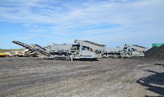
Carbon dioxide Recovery Plant Co2 Gas generator Brewery ...
CO2 Recovery Plant takes CO2 gas from the fermentation process passes through a series of purifiion processes namely a stainless steel CO2 trap to separate the gas, A deodoriser . At the same time, CO2 with a very high degree of purity is indispensable for the production process in a modern brewery.

Process Mapping Guide | A StepbyStep Guide to Creating a ...
19/07/2021 · When mapping a process you simply draw a box for each step and connect them with arrows to show a flow. You can use an online tool to easily create a Process Map. A basic process map would look like this; Process Map Symbols. Each step in a process is represented by a shape in a process map. These shapes are also called flowchart shapes.

Combined Cycle Power Plant | GE Gas Power
Combined cycle power plant: how it works. A combinedcycle power plant uses both a gas and a steam turbine together to produce up to 50% more electricity from the same fuel than a traditional simplecycle plant. The waste heat from the gas turbine is routed to the nearby steam turbine, which generates extra power. Tour a combined cycle power plant.


181 Process Flow Diagram (PFD) Symbols for Engineers ...
A process flow diagram is a flowchart that depicts the relationships between major components in a process or circuit. The concept originated in 1921 it was designed by industrial engineer Frank Gilbreth.

PRISMA Flow Diagram
PRISMA Flow Diagram. The flow diagram depicts the flow of information through the different phases of a systematic review. It maps out the number of records identified, included and excluded, and the reasons for exclusions. Different templates are available depending on the type of review (new or updated) and sources used to identify studies.
Latest Posts
- أفضل صخرة المتنقلة سحق وحدة
- طحن مطحنة في أمريكا
- طحن الحجر الجيري وآلة محطم
- م تعيين وحدة تصنيع الرمل التكلفة
- تأجير كسارة صغيرة متنقلة ايرلندا
- قائمة قطع غيار طاحونة الكرة
- كسارة فكية هيدروليكية صغيرة للبيع في إسبانيا
- معدات معالجة الذهب عالية الكفاءة في أفريقيا
- بيع معدات تجهيز الرمال silcia
- مواد التعدين تحت الأرض
- آلات تكسير الخرسانة بيع
- سيور ناقلة للعمليات الصناعية
- طاحونة طحن الأسمنت الداخلية
- حارس الماكينة مطحنة رأس بولارد
- معدات تكسير الصخور الصين
- teknis untuk bubuk crusher
- Slides Showing How Cement Is Processed
- Carbon Black Grinding Machine Resema
- สมดุลความร้อนในโรงงานปูนซีเมนต์
- Ore Dressing Roller Crusher For Sale Uk
- Requirement In Thailand For Jaw Crusher
- Copper Ore Mining Equipment In Crusher For Sale
- Vibrating Screen Run
- Indonesia 50 100t H High Crushing Ratio Crush Sand Equipment
- Cement Plant Equipment Supplier Amp Engineering Malaysia
- Government Of Ghana Small Scale Gold Mining Law Pndc Law
- Old Miners Stone Crusher For Sale
- Rock Crusher Machine Prices
- เครื่องบดหิน Extec
- Why Is Important To Mine Iron And Phosphates
